
Removal of the old bearing
After removal of the half shaft it is necessary to mount the shaft in a lathe and turn down the bearing retaining collar until about 0.010 inch remains when it is easy to split and remove the remaining collar with a chisel, without damage to the shaft surface. It is important that the integrity of the shaft surface at this point is protected because eventually a new retaining collar will have to be pressed on to the shaft and it is only the interference fit between the collar and shaft plus the bearing fit, which retains the road wheel and bearing assembly. An alternative would be to use an angle grinder or cutter and remove the collar without damaging the shaft. Using a lathe does enable the straightness of the shaft to be checked as any out of truth will wear both axle and wheel bearings and take its toll on the half shaft splines. Once the retaining collar is removed the bearing spring (belleville washer) can be discarded as can the bearing spacer ring, which is loose in the bearing housing.
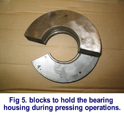
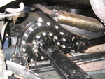
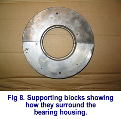
At this point it is necessary to mount the shaft in a hollow hydraulic press bed and provide a suitable support for the bearing housing whilst the shaft is pressed through, and therefore off the bearing. My own supports are made of a steel circular section some 9 inches in diameter and 1.250 inch thick. This circular section was then machined to fit around the bearing housing with an integral step, this step was lathe-turned to fit the step in the bearing housing and then finally the circular section was sawn across the centre. This tool then forms two "U" shaped sections, which completely surround and support the bearing housing whilst the pressing operation is in progress.
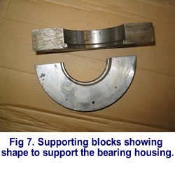
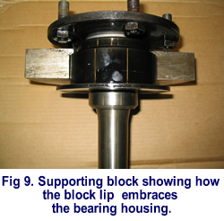
It is very important that the flange of the bearing housing, which is about 0.125 inch thick, is not used to support the housing during pressing operations. The bearing housing STEP must take the load and if any load is applied to the flange, distortion and subsequent water entry will result. There is also a very serious possibility of the flange breaking away at some time in the future.
By this time the wise owner will no doubt realise the wisdom of replacing these bearing whilst the car is in his / her own garage or with a specialist of their choice and not risking a distress purchase out on the open road.
Fitting of the New Bearing RG5365P
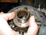
Once the shaft has been pressed off the bearing it is necessary to recover the bell shaped spacer from the flange end of the shaft. This spacer positions the bearing the correct distance from the end of the shaft, and in doing so, sets the final running clearance between the brake back plate and the edge of the brake drum, clean off the spacer faces and the opposing half shaft face and replace the spacer immediately.
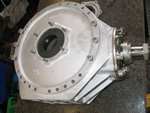
Press out the old bearing from the housing. Examination of the housing flange will no doubt show that some water ingress has taken place and rust is present on the flange face.
Initially check the flange of the bearing housing to ensure it is flat and not distorted, if any out of truth is present it MUST be faced off, keeping any metal removal to within approximately 0.005 inch.
Bearing Protrusion
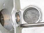
Measure the thickness of the bearing and the actual depth of the bearing housing to the internal step where the bearing locates. These measurements will be approximately 1.5615 inch ( 39.66mm) if the bearing housing flange has not been faced off. The measurements finally will require adjusting by machining either the flange face or housing internal step to ensure that the bearing is thicker than the housing depth by 0.001 inch. In other words when the bearing is fitted to the housing it should protrude by 0.001 inch. This protrusion allows for a thin film of sealer to be applied to the bearing housing flange, and also ensures that when the bearing housing is rebolted to the spigot plate the plate will actually contact the bearing and stop any bearing end float or looseness. In simple terms the bearing will be trapped hard between the spigot plate and bearing housing. Normally, even making allowances for truing up the housing flange, no more than 0.0010 inch needs removing from either the flange or the housing step.
Spigot Plate
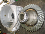
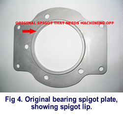
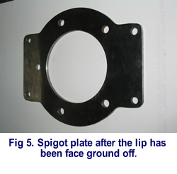
Next, examination of the bearing spigot plate will show a location protrusion or spigot, which needs machining off the plate and the plate face grinding to finish. This protrusion originally contacted the original bearing spacer ring, which has now been discarded, it should also be said that the protrusion did provide a spigot to assist in centralising the assembly. However the bearing housing attachment bolts and their holes are very accurate in size and circular pitch dimension, and therefore centralisation and the retention under load appears well catered for, even when the assistance of the spigot is lost. Note that it is necessary to dismantle the rear brake assembly to extract the bearing spigot plate!!
This spigot plate is shown in most parts lists on page K1 and is the item shown nearest the half shaft splines, it is not individually numbered, and the illustration does not show the spigot section on this plate. The bearing spacer ring, to be discarded, is also show on page K1 and is the second item inwards from the half shaft splines. The plate spring (belleville washer) also to be discarded is shown as the fourth item from the splined end of the shaft.
| << Previous Page | Next Page >> |