Fitting the bearing
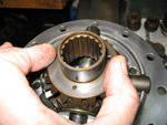
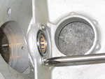
Having prepared the bearing housing it is possible now to press the bearing into the housing, taking care to only exert pressure on the OUTER bearing track. Then after making sure that the original bell shaped spacer and new spacer are both positioned on the half shaft beforehand, the shaft can be pressed through the centre of the bearing and its housing. Make sure the original bell shaped spacer is orientated correctly with its large diameter against the flange of the half shaft.
When pressing the bearings onto the shaft journal, the bearing MUST be supported by its INNER track, certainly not the housing flange, and the applied pressure, on the end flange of the half shaft, must be in the region of 6 to 10 tons. Following this operation a new bearing retaining collar part number GB 4956P must be pressed onto the shaft with a minimum pressure of 15 tons and preferably 20 tons. Note that the retaining collar will be about 0.125 inch short of fully engaging the half shaft bearing journal when it has been pressed into place.

In order to visualise both the bearing and the collar pressing operations, the half shaft flange end, that is the end where the wheel lug studs are positioned, is upwards and takes the force of the hydraulic pressing ram, whilst both bearing and /or collar are in contact with a piece of tubular steel, which is supported by the cross beams of the press bed. The aforementioned piece of tubular steel needs to be made wide enough to be supported by the cross beams of the press bed and thick enough to stand 20 tons, that is about 0.750 inch! In addition it needs a raised section or upstand of approx 0.250 inch, some 2.150 inch (54.61 mm) outside diameter and the whole block needs boring through the centre 1.80 inch (45.72 mm), which makes it a tube. Visually this looks like a large steel ring with a smaller ring placed on the top. The upstand or smaller ring is sized so that it contacts the INNER bearing track or collar depending on which operation is being performed, and the bored hole allows it to pass over the 1.772 inch (45 mm) half shaft diameter where the bearing is fitted.
After the bearing and retaining collar are fitted, the half shaft assembly can be replaced once the bearing spigot plate has been refitted.
Building up
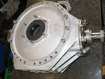
Clean the face of the axle tube. If you have removed the brake back plate do NOT forget to replace it on the axle tube before proceeding further. Do not on any account attempt to paint the outside edge of the bearing housing flange before the assembly has been replaced. The outer flange of this housing is an exact fit inside of the bearing spigot plate and paint will only be shed off and prevent the mating flange face surfaces from contacting.
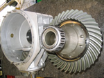
Coat the bearing housing flange with a very light coat of sealer. Enter the half shaft very carefully into the axle tube and engage the axle bevel wheel splines. Be careful when conducting this exercise not to damage the axle leather oil seal through which the half shaft splines must pass. Position the five bolts through the bearing plate and onto the axle tube fit the special spring washers and nuts and tighten. Do NOT use any other bolts except the originals.
You will need to centralise the brake adjuster and brake shoes as per the manual. It is vital that the adjuster is centralised BEFORE the shoe inter linkage is fitted. Then replace the brake back plate onto the four studs, then the adjuster wheel, then its lock nut, followed by the actuator rubber. Note there is a steel washer then a rubber between the rear of the adjuster and the back plate.
If the brake adjuster is disassembled, mark one adjuster tappet and one end before stripping, the tappets are handed!!! The brake actuator can be stripped by first removing the tin end cap. Removing the actuator tappets complete with ROLLERS after displacing the split pins and then pushing the rod and wedge outwards. Do not lose, or forget the return spring fitted behind the wedge. Refit any adjuster or actuator.
Finally build up the foundation brakes completely, fit the brake drum and adjust the brakes. Reconnect the brake rod to the equaliser and ensure the rubber boot is positioned correctly on the actuator. Refit the road wheel.
| << Previous Page |