
NOTE. The bore of both bearing and collar MUST be lubricated with engine oil before being pressed onto the half shaft.
Dismantling components and removing half shaft
Remove road wheel, brake drum, disconnect the brake rod at the equaliser, remove the brake shoes and inter-shoe linkages. Undo the five nuts holding the axle tube to the bearing retaining plate / bearing housing, undo the four nuts holding the brake back plate. Note the bolt heads are prevented from rotating, so all these nuts will come off.
Take the lock nut off the brake adjuster wheel, to do this slacken the adjuster right off until it will not turn any more, after removing the lock nut unscrew the brake adjuster wheel, it is threaded just like the lock nut.
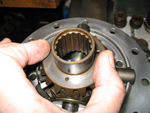
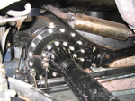
Move the brake actuator rubber inwards along the brake rod and then move the brake back plate off its four studs and onto the axle tube. Tap the flange of the half shaft to free the bearing housing and half shaft, and withdraw the assembly from the axle, collecting the loose brake carrier which is still bolted to the bearing retaining plate. Collect the five holding bolts.
Note at this point that of the five retaining bolt holes, the ODD hole is facing towards the Brake ADJUSTER. If you don’t remember this when assembling, you will have to strip the assemblies apart again!!!!
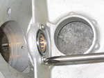
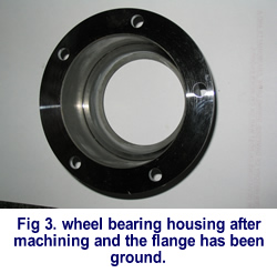
First undo the four nuts, bolts and spacers holding the bearing retaining plate to the brake carrier. Do not fail to collect the spacers. Now you will see the bearing spigot plate which has a protrusion on its inner face, this needs machining off and the plate just face-grinding on BOTH sides to clean it up and is discussed later. Note that this spigot plate has a taper lead on the opposite face to that face with the protrusion this taper face goes towards the axle.
Clean the brake carrier and assemble the machined plate to the carrier with the four nuts, bolts, SPACERS and spring washers. Remember taper face towards axle, and odd bolt hole adjacent to the brake adjuster.
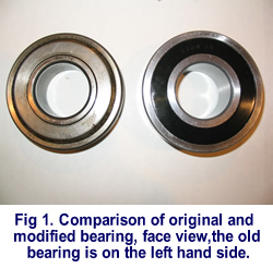
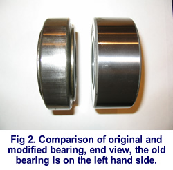
The replacement bearing must not be allowed to end float within the bearing housing and will need a protrusion from the housing when the bearing is fitted of at least 0.001 inch. This amount allows a zero end load when the bearing housing flange has been covered in sealer and the assembly fitted to the axle. The various workshop manuals describe the removal of the half shaft assemblies, which are removed complete with bearings and bearing housings, and also a spigot plate and bearing spacer ring. In the case of a straight forward replacement of the original type bearing it was always intended that the bearing spacer ring was to be face ground in order to just pre-load the new bearing, as previously mentioned. This is a point often disregarded when the original bearings are replaced and in particular when they are replaced as a result of a failure on the road.
In the case of this suggested bearing conversion this spacer ring is discarded.| << Previous Page | Next Page >> |