
Fitting the new bearing RG8104P
 |
 |
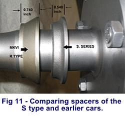 |
Next, press out the old bearing from the housing. Examine the bearing housing and check it with a straight edge to ensure the flange is not warped. If there is evidence of distortion have the flange face ground. Then have an equivalent of the metal depth ground from the flange compensated, by then removing the same depth from the internal abutment where the bearing contacts. This allows the bearing to sit back in the housing rather than protrude. Originally the dimension, or off set, from the half shaft outer flange to the faced flange of the bearing housing is 2.60 inch to about 2.620 inch when the bearing housing has been fitted. This dimension was recorded on six shafts and bearing assemblies taken from different model S type cars.
Fitting the bearing
 |
 |
 |
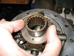
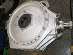
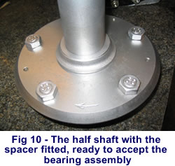
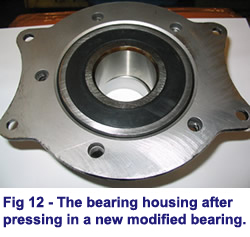
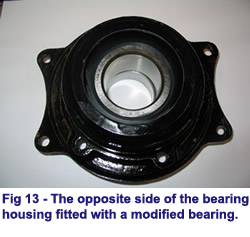
Having prepared the bearing housing it is possible now to press the bearing into the housing, taking care to only exert pressure on the OUTER bearing track. Make sure that the original bell shaped spacer has been positioned on the half shaft beforehand and it is orientated correctly with its large diameter against the flange of the half shaft. The shaft can then be pressed through the centre of the bearing and its housing. Fig 12 and Fig 13 show a bearing after it has been pressed into the housing.
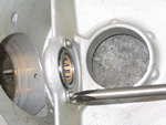
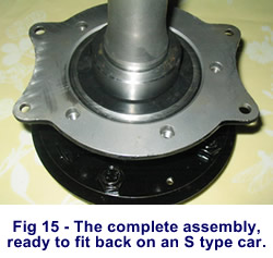
When pressing the bearings onto the shaft journal, the bearing MUST be supported by its INNER track, certainly not the housing flange. The applied pressure, on the end flange of the half shaft will need to be in the region of 3 to 5 tons to allow the bearing to seat. Following this operation a new bearing retaining collar part number GB 4956P must be pressed onto the shaft, and then a minimum pressure of 15 tons and preferably 20 tons applied. In order to visualise both the bearing and the collar pressing operations, the half shaft flange end, that is the end where the wheel studs are positioned, is upwards and takes the force of the hydraulic pressing ram, whilst both bearing and /or collar are in contact with a piece of tubular steel, which is supported by the cross beams of the press bed. The aforementioned piece of tubular steel needs to be made wide enough to be supported by the cross beams of the press bed and thick enough to stand a 20 ton load. In addition it needs a raised section or upstand of approx 0.250 inch, some 2.150 inch (54.61 mm) outside diameter and the whole block needs boring through the centre 1.80 inch (45.72 mm), which makes it a tube. Visually this looks like a large steel ring with a smaller ring placed on the top. The upstand or smaller ring is sized so that it contacts the INNER bearing track or GB 4956P collar, depending on which operation is being performed. When the bearing is being supported the bored hole allows the tool to pass over the 1.772 inch(45 mm) half shaft diameter where the retaining collar is to be fitted. After the bearing and retaining collar are fitted, see Fig 15, the half shaft assembly can be replaced.
| << Previous Page |